PartGuys

    Advanced 3D Printing Technologies

    Industrial-grade additive manufacturing solutions for your most demanding projects

    Printed in-house in Livonia — 3D printing service in Michigan.
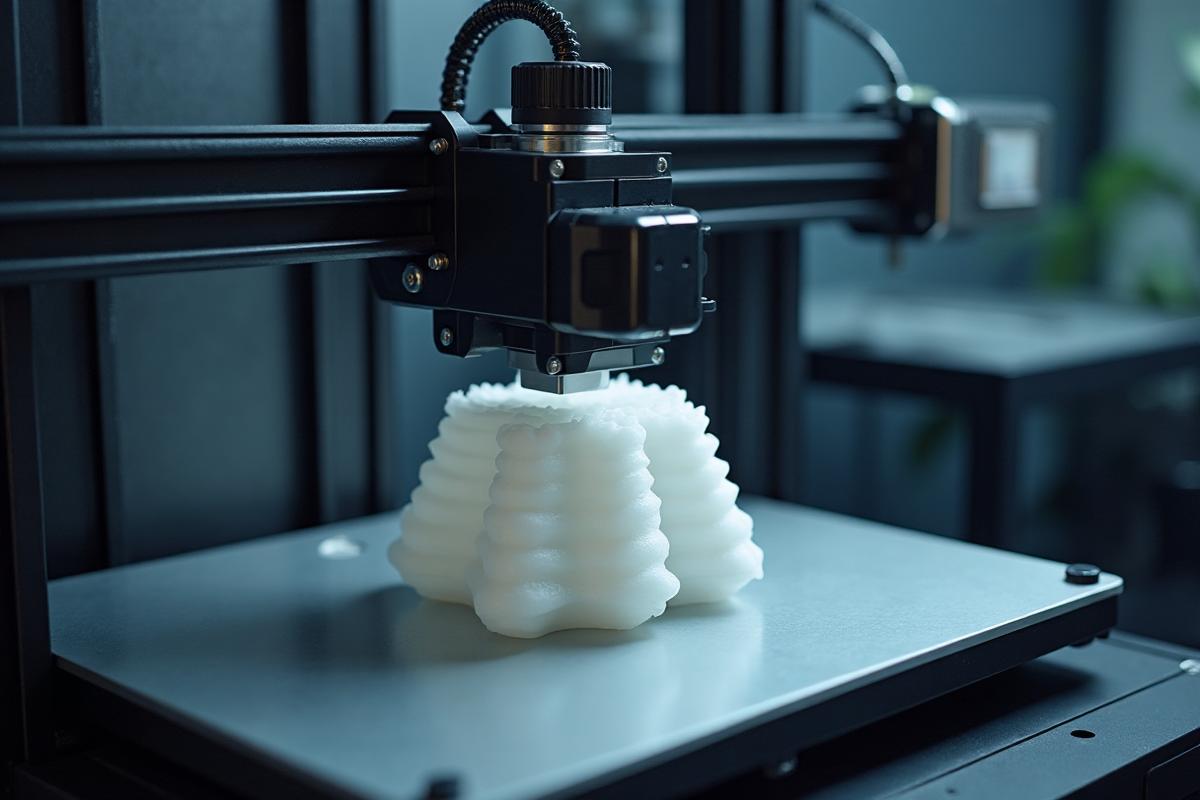
    SLS Technology

    Selective Laser Sintering - Complex geometries without supports
    FDM Technology

    Fused Deposition Modeling - Versatile prototyping and larger parts
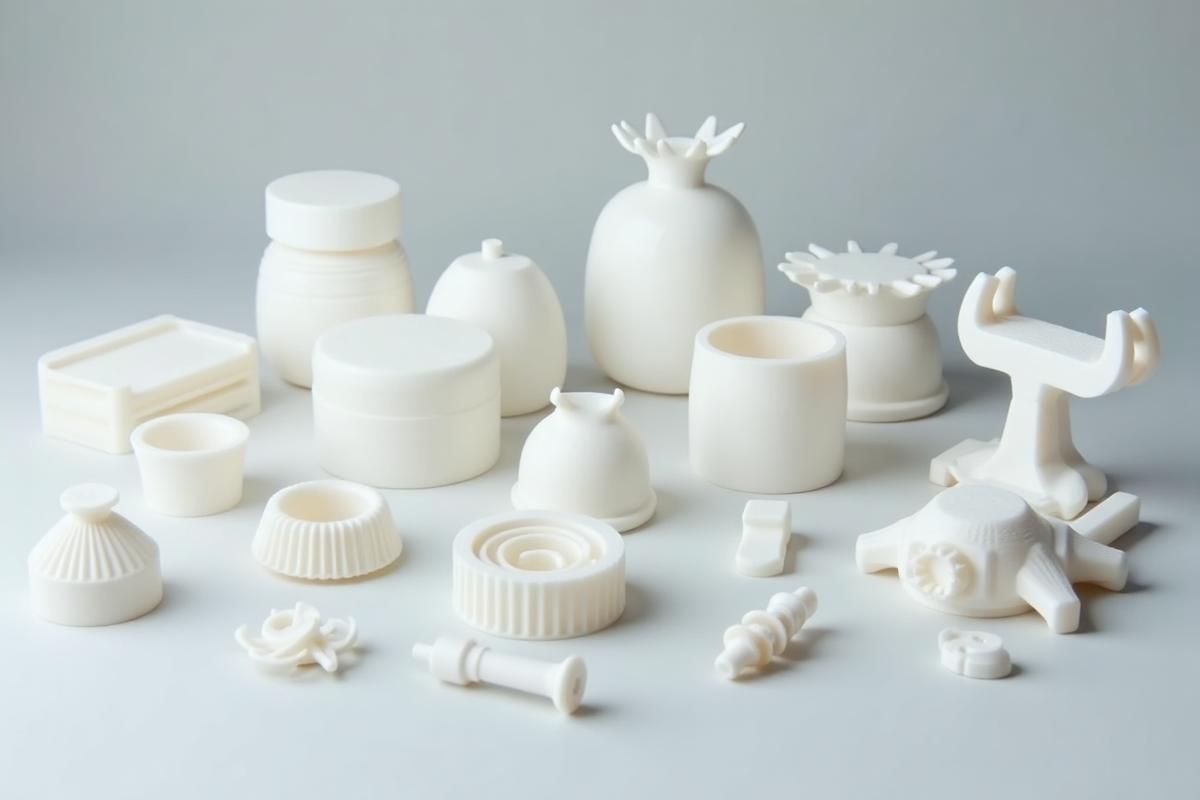
    Production parts showcase

    Production-ready parts across our SLS and FDM lineup

    Explore our advanced additive manufacturing technologies. Each process offers unique advantages for different applications, from rapid prototyping to end-use production parts.

    ⚡

    SLS
    Selective Laser Sintering

    Powder-based 3D printing using laser sintering for complex geometries without support structures

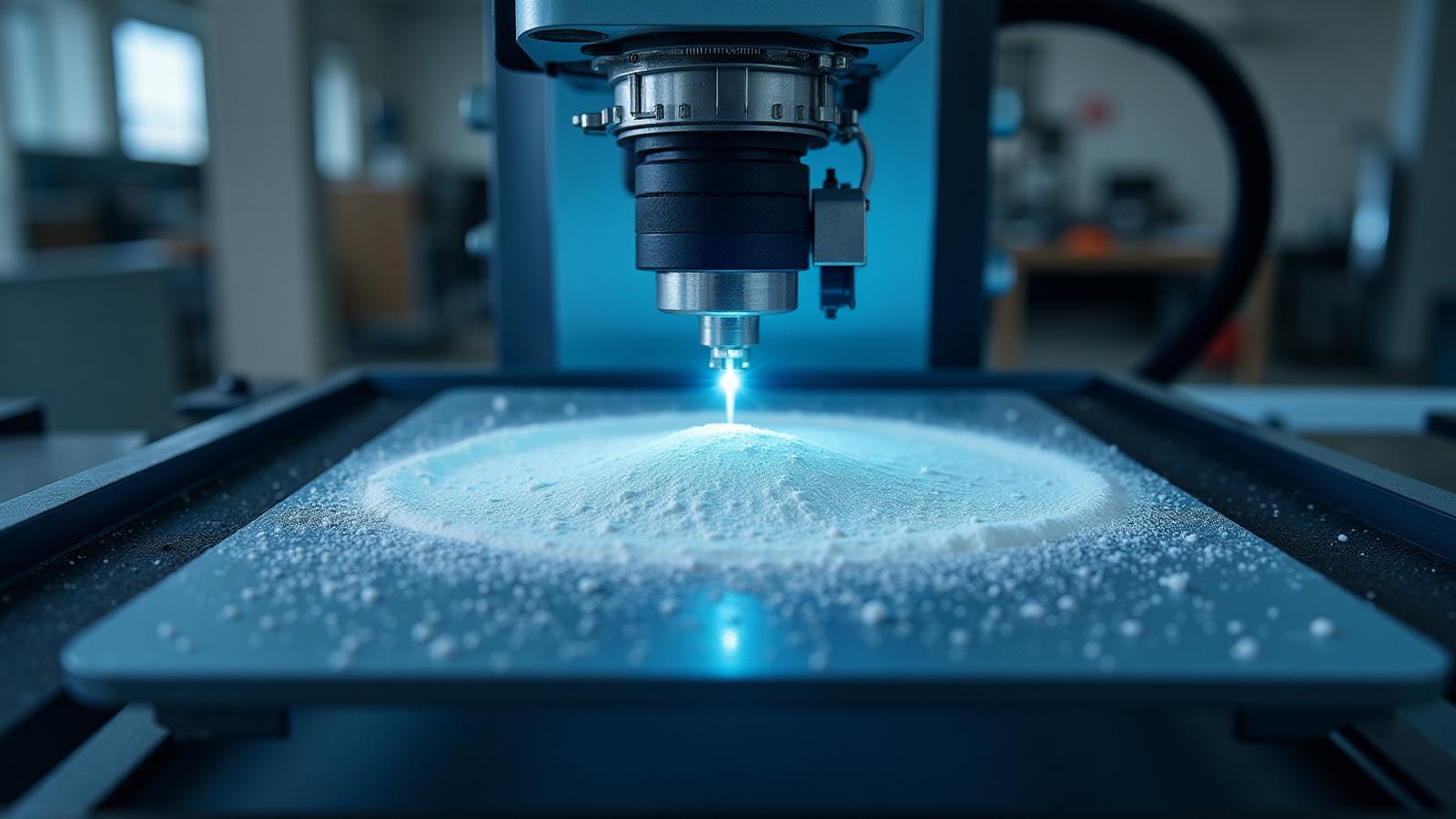
    SLS 3D printer machine

    Industrial SLS equipment for powder-based printing

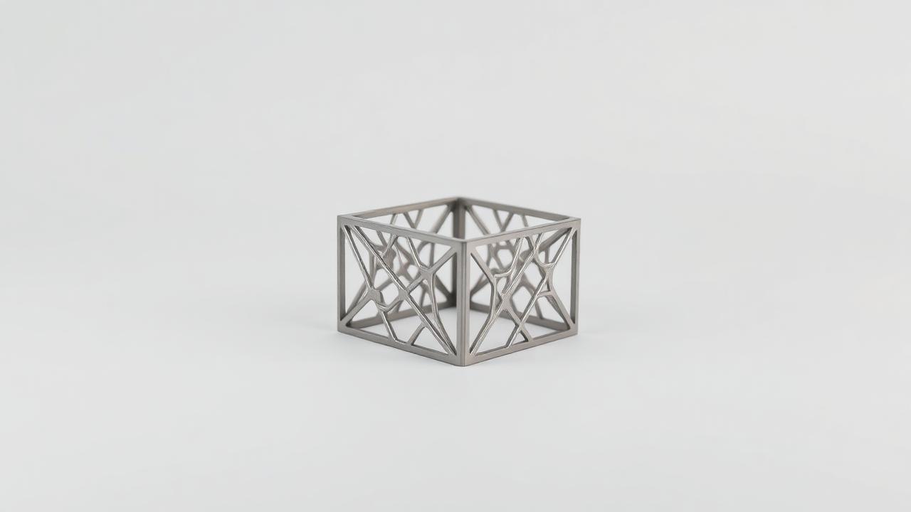
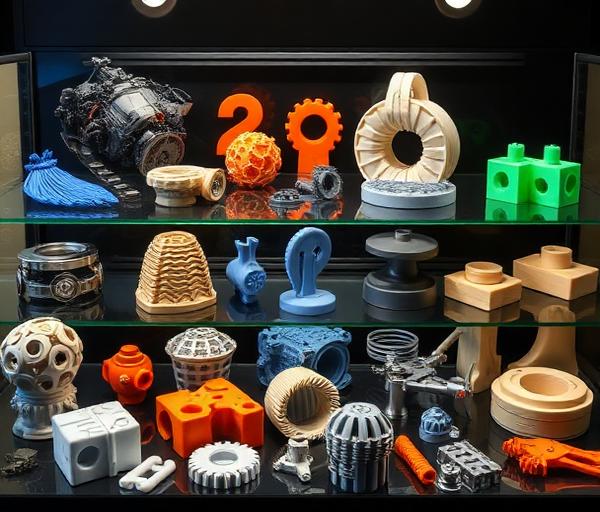
    SLS printed parts

    Complex geometries achievable with SLS technology
    📏
    Build Volume
    165 × 165 × 300 mm
    🎯
    Accuracy
    ±0.3 mm or ±0.3%
    ⏱️
    Lead Time
    Economy 5 business days, Priority 3 business days, Rush 1 business day (orders of $50 or more). Made in-house in Michigan.
    📊
    Layer Height
    0.1 - 0.15 mm
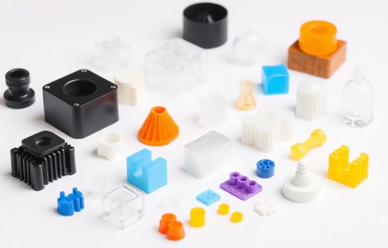
    3D printing material samples

    Available Materials

    Compatible materials optimized for SLS technology
    PA12 (Nylon 12)
    Details →
    PA12-GF (Glass-filled Nylon)
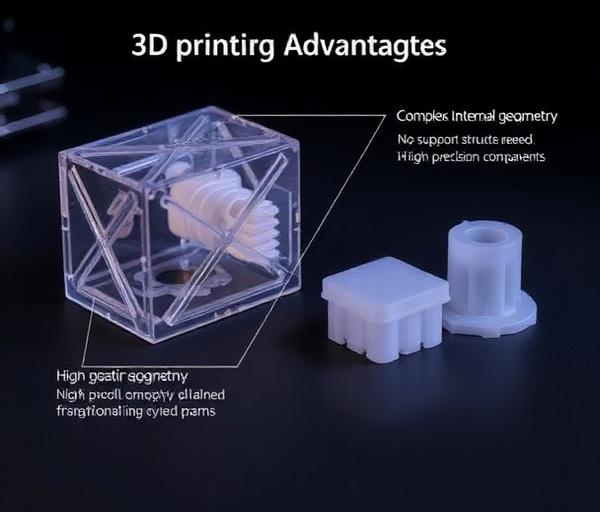
    3D printing advantages showcase

    Key Advantages

    Primary benefits of SLS technology

    No support structures required
    Complex internal geometries possible
    Excellent mechanical properties
    High part density and strength

    Considerations

    Important factors to consider for SLS
    Limited material selection
    Powder handling required
    Post-processing needed
    Higher cost per part
    3D printing use cases and applications

    Ideal Applications

    Perfect use cases for SLS technology
    Functional prototypes
    End-use parts
    Complex mechanical components
    Automotive parts
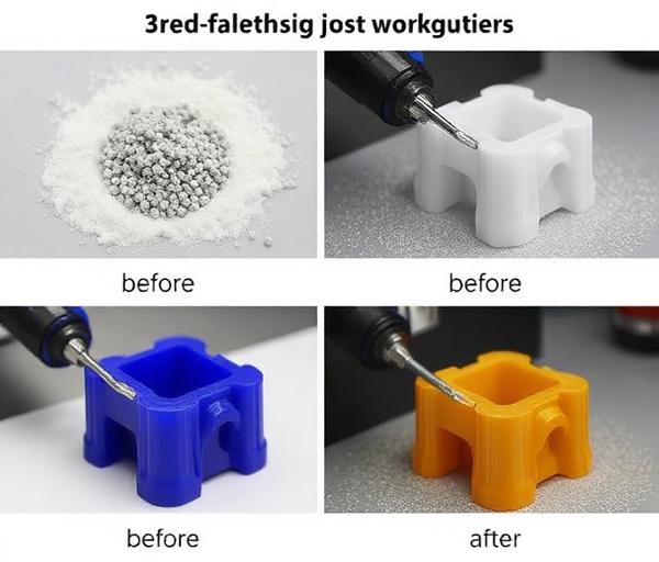
    Post-processing workflow for 3D printed parts

    Finishing Options

    Available post-processing services
    Powder removal
    Bead blasting
    Dyeing (black available)
    Machining if needed
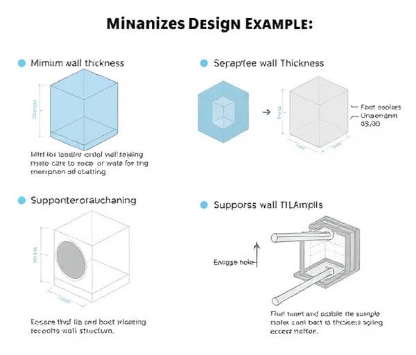
    Design guidelines and technical specifications

    Design Guidelines

    Essential design rules for optimal results

    Minimum wall thickness: 0.8mm
    Minimum feature size: 0.4mm
    Escape holes for trapped powder
    🔧

    FDM
    Fused Deposition Modeling

    Thermoplastic extrusion process ideal for prototypes, fixtures, and larger geometries

    FDM 3D printer

    Professional FDM printing for functional prototypes

    📏
    Build Volume
    256 × 256 × 256 mm
    🎯
    Accuracy
    ±0.5 mm
    ⏱️
    Lead Time
    6–7 business days standard; Priority and Rush on some materials
    📊
    Layer Height
    0.1 - 0.3 mm
    3D printing material samples

    Available Materials

    Compatible materials optimized for FDM technology

    ABS (Acrylonitrile Butadiene Styrene)
    ASA
    PA6-GF (Glass Fiber Nylon 6)
    PAHT-CF (Carbon Fiber Nylon)
    PC FR
    PETG (Polyethylene Terephthalate Glycol)
    PLA (Polylactic Acid)
    TPU 90A
    3D printing advantages showcase

    Key Advantages

    Primary benefits of FDM technology

    Cost-effective
    Wide material selection (PLA, ABS, PETG, TPU, PAHT-CF, PA6-GF)
    Fast turnaround
    Good for large parts

    Considerations

    Important factors to consider for FDM

    Visible layer lines
    Support structures required
    Anisotropic properties
    Limited overhangs
    3D printing use cases and applications

    Ideal Applications

    Perfect use cases for FDM technology

    Concept models
    Visual prototypes
    Jigs and fixtures
    Larger functional parts
    Post-processing workflow for 3D printed parts

    Finishing Options

    Available post-processing services

    Support removal
    Sanding
    Painting
    Vapor smoothing (ABS)
    Design guidelines and technical specifications

    Design Guidelines

    Essential design rules for optimal results

    45° overhang rule
    Support structure planning
    Layer adhesion direction
    🎨

    Full Color SLA
    Full-Color Photopolymer Jetting
    New

    Photorealistic, full-color 3D printing in a single pass — up to 10 million colors baked directly into the part surface, no painting required.
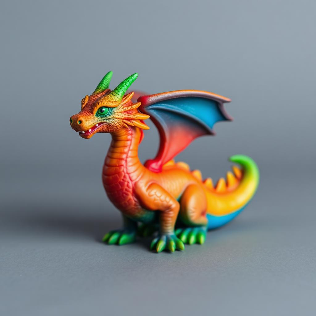
    Full color 3D printed figurine

    Photorealistic figurines with smooth color gradients
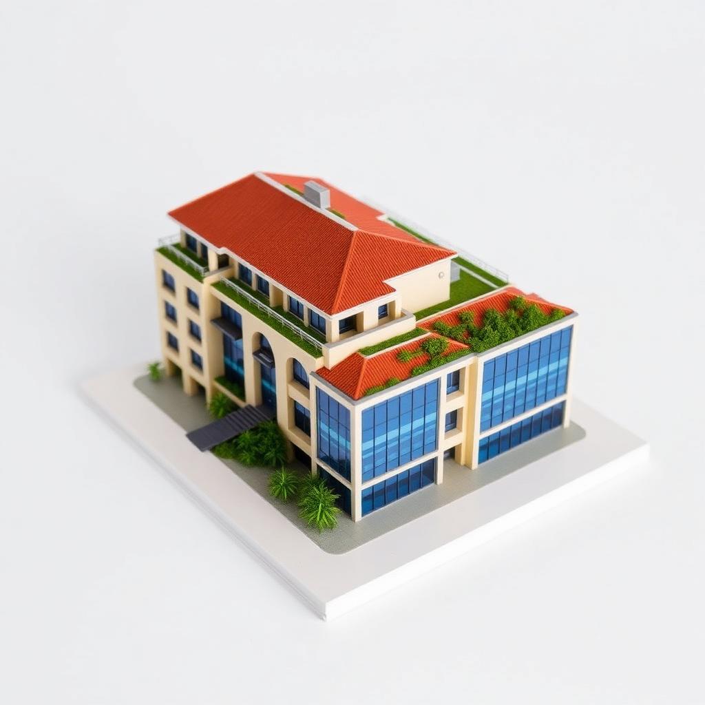
    Full color architectural model

    Multi-color architectural and product models

    📏
    Build Volume
    500 × 500 × 200 mm
    🎯
    Accuracy
    ±0.2 mm
    ⏱️
    Lead Time
    14–21 business days
    📊
    Layer Height
    ~0.027 mm
    3D printing material samples

    Available Materials

    Compatible materials optimized for Full Color SLA technology

    Full Color Resin (UV-cured photopolymer)
    3D printing advantages showcase

    Key Advantages

    Primary benefits of Full Color SLA technology

    Up to 10 million colors in a single print
    Photorealistic textures and smooth gradients
    Ultra-fine layer detail for collectibles and models
    Waterproof and UV-resistant finish

    Considerations

    Important factors to consider for Full Color SLA

    Longer lead time than in-house SLS/FDM (14–21 business days)
    Best for visual / display parts — not load-bearing structural use
    Requires a vendor-ready OBJ+MTL+texture ZIP or Meshy-generated textured GLB
    Large build envelope but oversized parts may need splitting
    3D printing use cases and applications

    Ideal Applications

    Perfect use cases for Full Color SLA technology

    Gaming figurines & collectibles
    Consumer product prototypes
    Architectural and scale models
    Medical and educational anatomy
    Post-processing workflow for 3D printed parts

    Finishing Options

    Available post-processing services

    UV-cure finishing (standard)
    Clear protective coating optional
    Smooth, ready-to-display surface
    Design guidelines and technical specifications

    Design Guidelines

    Essential design rules for optimal results

    Minimum wall thickness: 1.5 mm
    Minimum feature size: 0.5 mm
    Upload as ZIP with model + textures for best color fidelity
    🪙

    Investment Casting
    Lost-Wax Investment Casting

    Metal parts produced by 3D-printing a burnout pattern, investing it in a ceramic shell, and pouring molten metal. Combines additive design freedom with true metal mechanical properties.
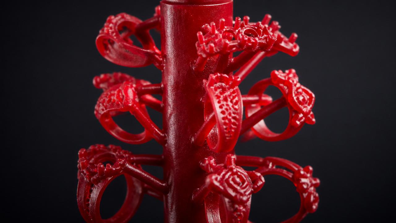
    Red wax pattern tree of jewelry rings on a central sprue

    Wax pattern tree — the burnout master for each cast run
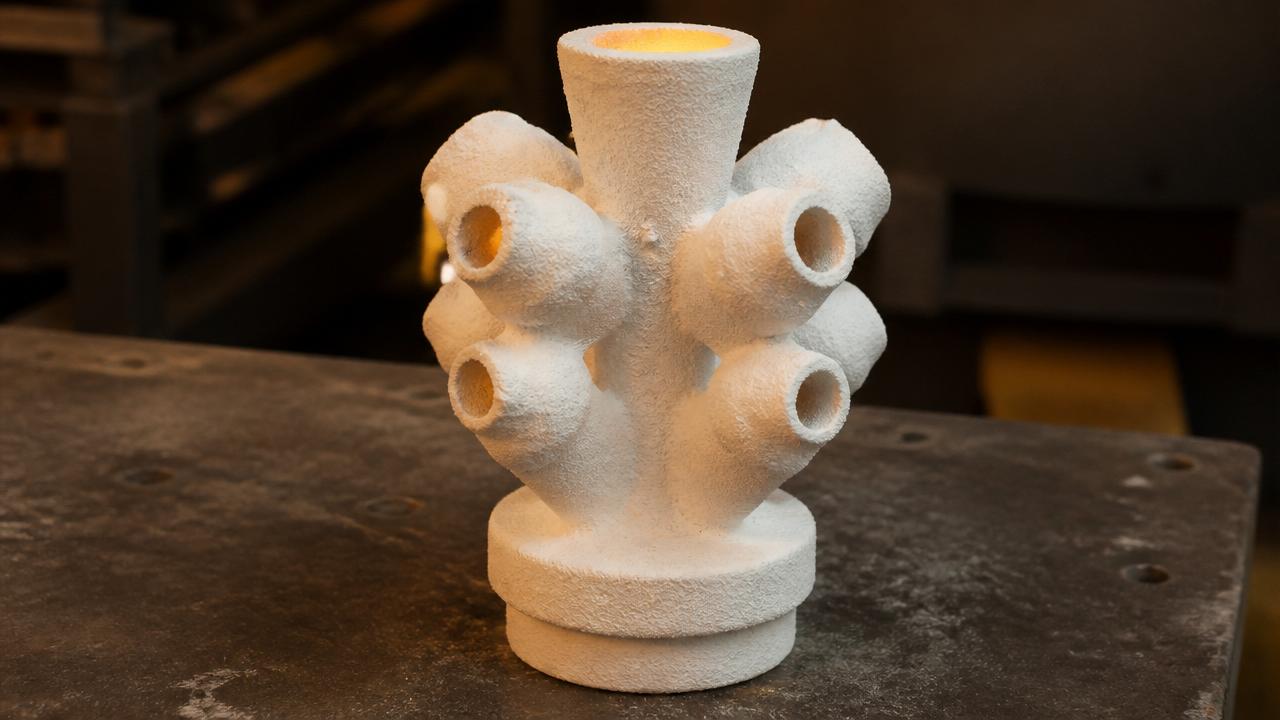
    Ceramic investment shell after wax burnout

    Ceramic shell after burnout — ready for the pour
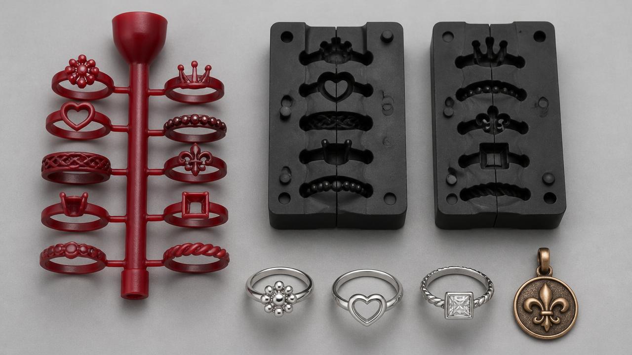
    Jewelry investment casting workflow with wax tree, silicone molds, and finished silver and bronze pieces

    Jewelry-grade molds & precious-metal finish work
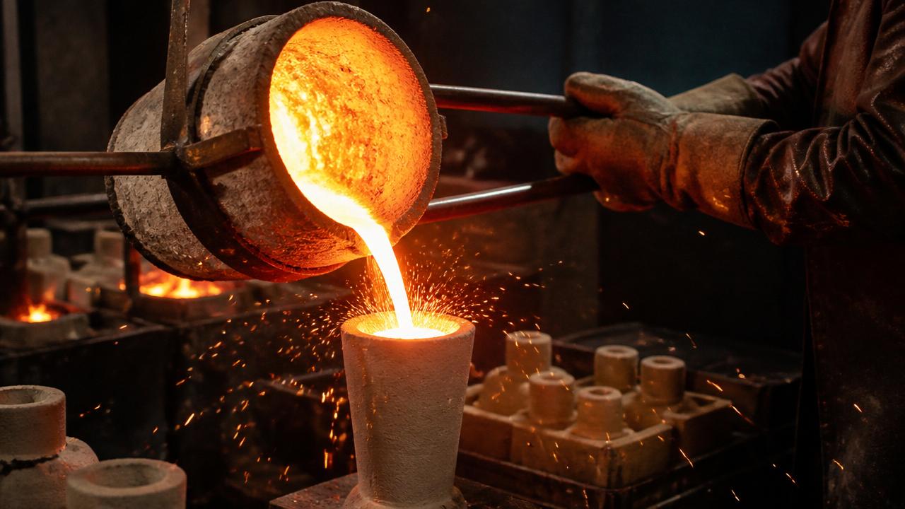
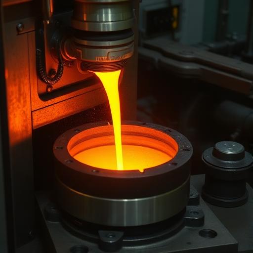
    Molten bronze being poured into a ceramic investment flask

    Molten metal poured into the invested flask
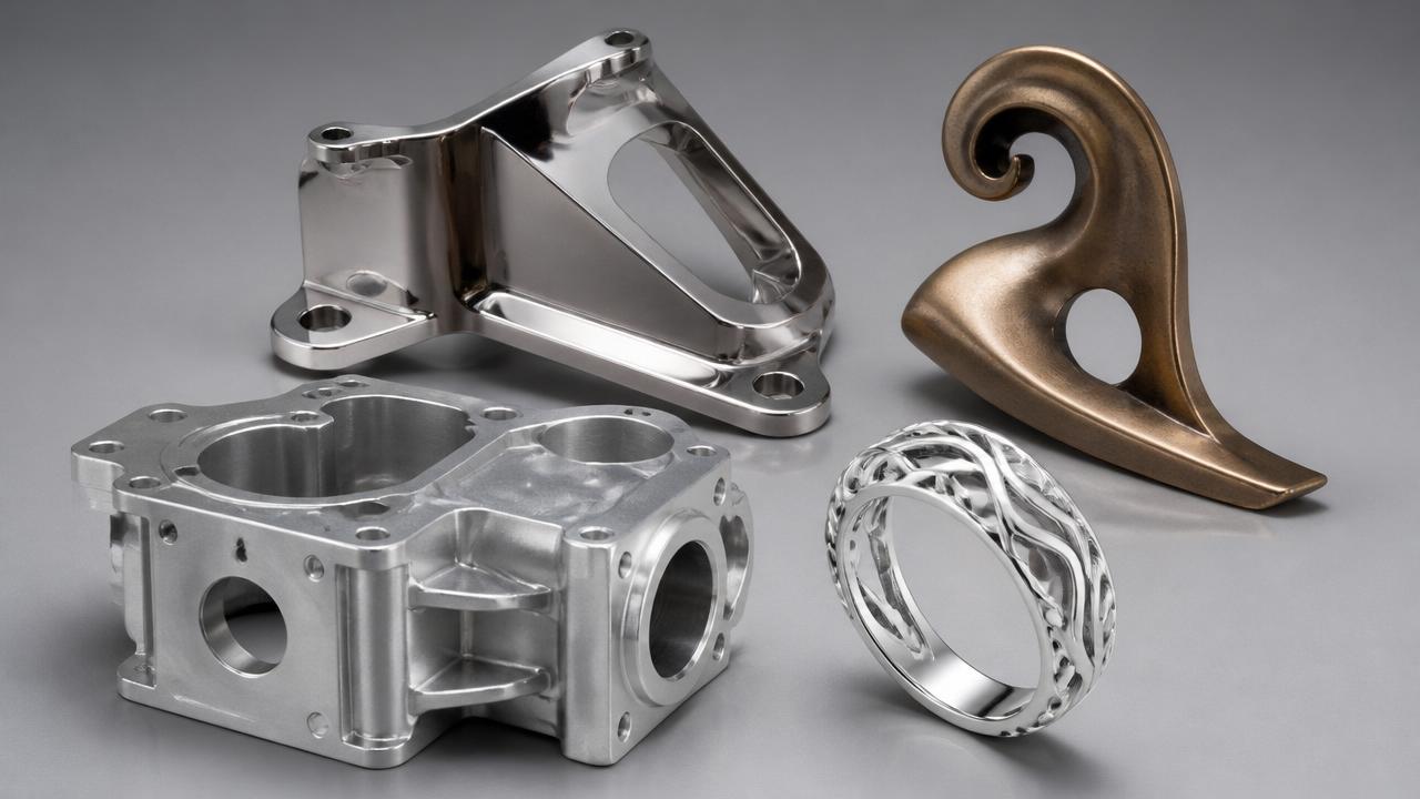
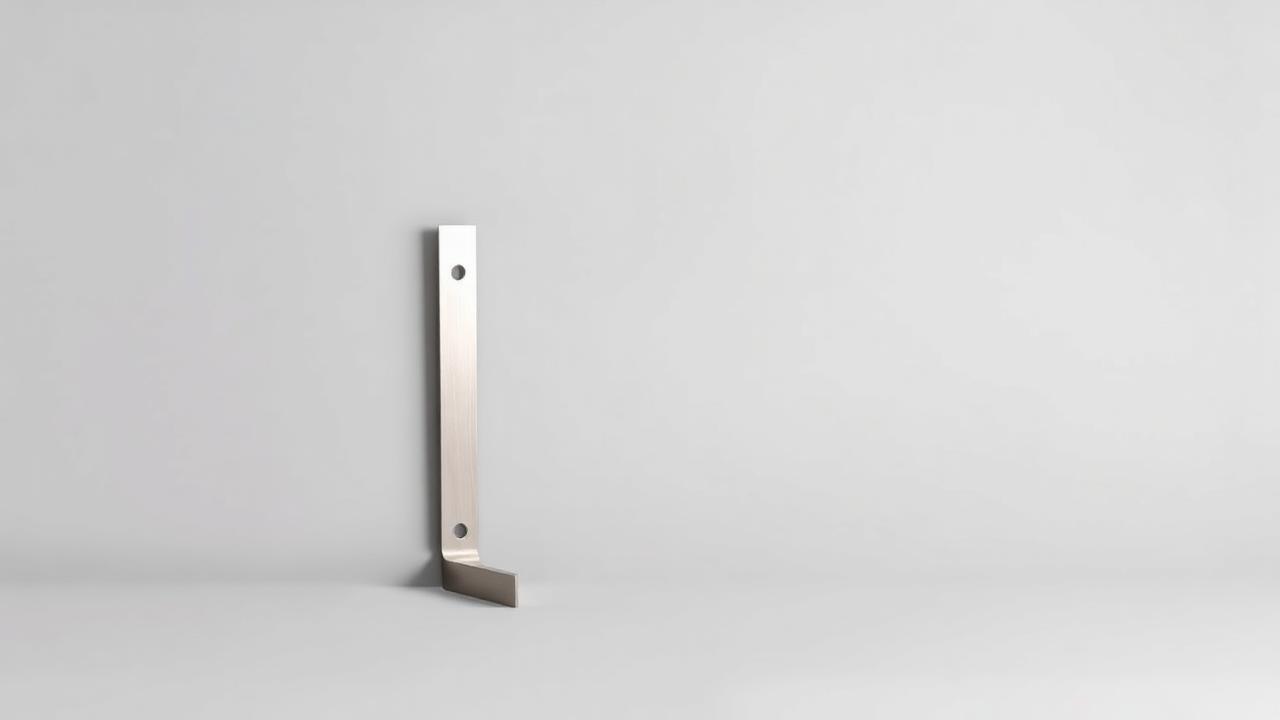
    Finished investment-cast stainless bracket, bronze sculpture, aluminum housing, and silver ring

    Finished cast parts: stainless, bronze, aluminum, silver

    📏
    Build Volume
    300 × 300 × 300 mm (max)
    🎯
    Accuracy
    ±0.5% (min ±0.15 mm)
    ⏱️
    Lead Time
    14–21 business days
    📊
    Layer Height
    Pattern-dependent
    3D printing material samples

    Available Materials

    Compatible materials optimized for Investment Casting technology

    Brass
    Bronze
    Copper
    Plated Brass
    Silver (92.5% Sterling)
    Gold (Solid)
    3D printing advantages showcase

    Key Advantages

    Primary benefits of Investment Casting technology

    True metal parts — aluminum, stainless, brass, bronze
    Excellent surface finish straight from the mold
    Complex geometries with minimal draft
    Low tooling cost vs. traditional casting

    Considerations

    Important factors to consider for Investment Casting

    Hard part-size cap of 300 × 300 × 300 mm — split or RFQ for anything larger
    Longer lead time than in-house SLS/FDM (14–21 business days)
    Shrinkage compensation applied automatically
    Uniform wall thickness strongly recommended
    3D printing use cases and applications

    Ideal Applications

    Perfect use cases for Investment Casting technology

    Low- and mid-volume metal parts
    Functional metal prototypes
    Replacement or legacy components
    Art, sculpture, and jewelry pieces
    Post-processing workflow for 3D printed parts

    Finishing Options

    Available post-processing services

    Media blast / tumble (standard)
    Machining of critical features
    Polishing and satin finishes
    Plating (nickel, chrome, gold, etc.)
    Design guidelines and technical specifications

    Design Guidelines

    Essential design rules for optimal results

    Minimum wall thickness: 1.5 mm
    Uniform wall thickness — avoid heavy/thin transitions
    Generous fillets on internal corners
    🧊

    MJF
    Multi Jet Fusion
    Partner

    Powder-bed process that fuses a whole layer at a time rather than tracing it with a laser. Faster than SLS on filled builds, isotropic, and the only route we have to full-color nylon.

    📏
    Build Volume
    284 × 380 × 380 mm (max)
    🎯
    Accuracy
    ±0.2 mm, then ±0.5% of length
    ⏱️
    Lead Time
    14 business days
    📊
    Layer Height
    0.08 mm
    3D printing material samples

    Available Materials

    Compatible materials optimized for MJF technology

    PA12 (Nylon 12)
    Details →
    PA12-GB (Glass-bead Nylon 12)
    PA12 Full Color (full-colour Nylon 12)
    3D printing advantages showcase

    Key Advantages

    Primary benefits of MJF technology

    Isotropic — the same strength in every direction
    Fine 80 micron layers hold small features
    No support structures required
    Full-color nylon available in a functional material

    Considerations

    Important factors to consider for MJF

    Matte, slightly grainy surface as printed
    Grey and black only in the unfilled nylon
    Longer lead time than our in-house SLS
    Trapped powder needs escape holes
    3D printing use cases and applications

    Ideal Applications

    Perfect use cases for MJF technology

    Production runs of functional nylon parts
    Color-coded assemblies
    Housings and enclosures
    Jigs and fixtures
    Post-processing workflow for 3D printed parts

    Finishing Options

    Available post-processing services

    Powder removal and bead blasting
    Black dyeing
    Vapor smoothing
    Design guidelines and technical specifications

    Design Guidelines

    Essential design rules for optimal results

    Minimum wall thickness: 0.75 mm supported, 1.0 mm unsupported
    Escape holes for trapped powder
    Full-color parts need 0.8 mm walls natural, 1.5 mm smoothed
    💧

    SLA
    Stereolithography
    Partner

    A laser cures liquid resin layer by layer. The smoothest surface and finest detail of any process we offer — the choice for appearance models, clear parts and master patterns.

    📏
    Build Volume
    790 × 790 × 590 mm (max)
    🎯
    Accuracy
    ±0.2% (min ±0.2 mm)
    ⏱️
    Lead Time
    14 business days
    📊
    Layer Height
    0.1 mm average, 0.025 mm minimum
    3D printing material samples

    Available Materials

    Compatible materials optimized for SLA technology

    Somos GP Plus 14122 (opaque white)
    Somos WaterShed XC 11122 (near-clear)
    Somos WaterShed Black (opaque black)
    3D printing advantages showcase

    Key Advantages

    Primary benefits of SLA technology

    Smoothest surface finish available
    Finest feature detail and crisp side walls
    Transparent parts when polished
    Excellent dimensional accuracy

    Considerations

    Important factors to consider for SLA

    Photopolymers, not production thermoplastics
    Heat ceiling around 49 C — not for hot environments
    Degrades under prolonged UV exposure
    Support marks need removing on cosmetic faces
    3D printing use cases and applications

    Ideal Applications

    Perfect use cases for SLA technology

    Appearance and presentation models
    Transparent housings, lenses and flow models
    Master patterns for casting
    High-accuracy fit checks
    Post-processing workflow for 3D printed parts

    Finishing Options

    Available post-processing services

    Support removal and UV post-cure (standard)
    Sanding and polishing
    Polishing to optical clarity
    Painting and priming
    Design guidelines and technical specifications

    Design Guidelines

    Essential design rules for optimal results

    Minimum wall thickness: 1.0 mm
    Specify which faces are cosmetic
    Avoid thick solid sections — they cure unevenly
    🏭

    SAF
    Selective Absorption Fusion
    Partner

    A production powder-bed process built for repeatability and throughput rather than one-offs. It is how we reach true polypropylene and bio-based PA11.

    📏
    Build Volume
    315 × 208 × 293 mm (max)
    🎯
    Accuracy
    ±0.3 mm or ±0.3% of the longest axis, whichever is larger
    ⏱️
    Lead Time
    14 business days
    📊
    Layer Height
    0.1 mm
    3D printing material samples

    Available Materials

    Compatible materials optimized for SAF technology

    PA11 (bio-based Nylon 11)
    PP (Polypropylene)
    3D printing advantages showcase

    Key Advantages

    Primary benefits of SAF technology

    Built for repeatable production volumes
    Genuine polypropylene — chemical resistance and weldability
    Bio-based PA11 from castor oil
    Strong Z-direction properties for a powder-bed process

    Considerations

    Important factors to consider for SAF

    Two materials only — PA11 and polypropylene
    Matte, grainy surface
    Heat performance falls away under load
    Grey and black only
    3D printing use cases and applications

    Ideal Applications

    Perfect use cases for SAF technology

    Production runs of end-use parts
    Ducting, manifolds and fluid housings
    Chemically resistant components
    Living hinges and snap-fits
    Post-processing workflow for 3D printed parts

    Finishing Options

    Available post-processing services

    Powder removal and bead blasting
    Dyeing to black
    Design guidelines and technical specifications

    Design Guidelines

    Essential design rules for optimal results

    Minimum wall thickness: 1.0 mm
    Escape holes for trapped powder
    Design for low stiffness in PP — add ribs, not thickness
    RFQ · Quote in 24 h

    Managed Partner Network

    Six additional manufacturing processes available through our managed supply chain. These run on a request-for-quote basis — share your part and we'll confirm pricing, lead time, and certification.
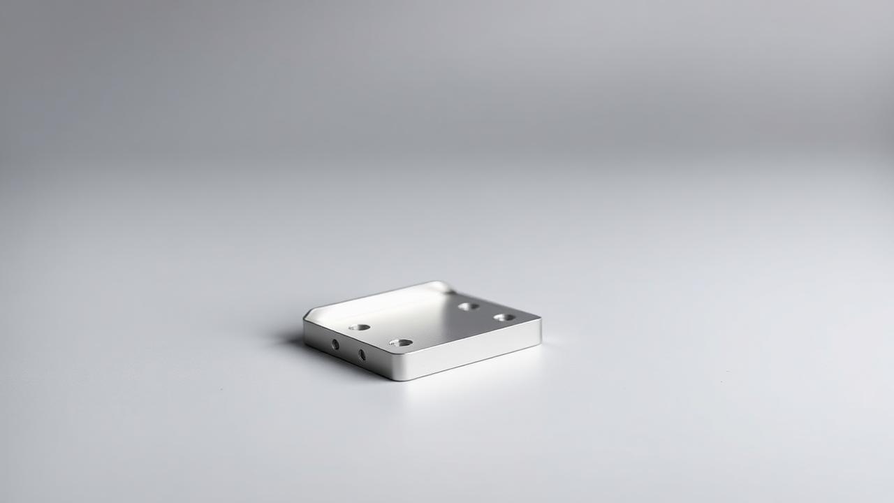
    CNC Machining
    RFQ

    01

    CNC Machining

    Plastic and metal precision machining

    Lead time:
    From 4 days for standard parts
    Tolerance:
    ±0.05mm / 100mm typical · ±0.025mm / 100mm available
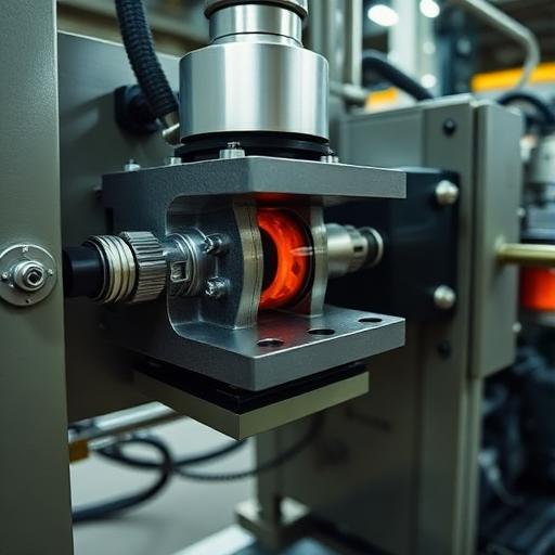
    Injection Molding
    RFQ

    02

    Injection Molding

    Rapid tooling to full production

    Lead time:
    Tooling from 2 weeks (rapid) · 5–8 weeks (production)
    Tolerance:
    Per-resin SPI tolerances
    Sheet Metal Fabrication
    RFQ

    03

    Sheet Metal Fabrication

    Laser cutting, bending, welding

    Lead time:
    From 5 days for standard parts
    Tolerance:
    ±0.2mm / 100mm typical
    Metal 3D Printing
    RFQ

    04

    Metal 3D Printing

    DMLM in flight-grade alloys

    Lead time:
    From 3 days print · post-processing additional
    Tolerance:
    ±0.3mm / 100mm typical · post-machining for tighter
    Vacuum Casting
    RFQ

    05

    Vacuum Casting

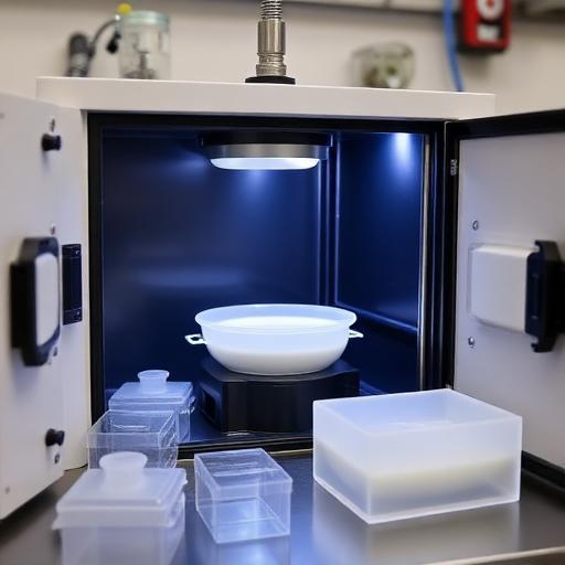
    Polyurethane casting, tooling-free

    Lead time:
    From 5 days
    Tolerance:
    ±0.3mm / 100mm typical
    Die Casting
    RFQ

    06

    Die Casting

    Aluminum, zinc, magnesium alloys

    Lead time:
    From 10 days for production runs
    Tolerance:
    ±0.3mm / 100mm typical (as-cast) · post-machining for tighter

    Ready to Get Started?

    Upload your 3D files and get instant pricing across all our technologies. Our system will help you choose the best process for your specific requirements.